This internal workshop example shows several useful stages of a CNC project: testing settings and fit, making a full-size prototype, arranging repeated parts on sheet material, separating the machined sections and reviewing a personalised board after CNC work.
The work was produced through the earlier CNC offering before the Wood to Spec brand launched. It is presented as a workshop demonstration, not as a Wood to Spec customer commission, review or testimonial.
What the demonstration was exploring
The design is a round solitaire board with a circular arrangement of playing-piece pockets, a routed channel and engraved details. The available workshop photographs show how those visible features moved from isolated tests into a complete board layout and then into repeated machining.
No numerical fit, tolerance or production result is claimed here. A photograph can show the physical stage and visible geometry, but it cannot establish the exact settings used, the measured result or suitability for another material without the supporting records.
1. Settings and fit test
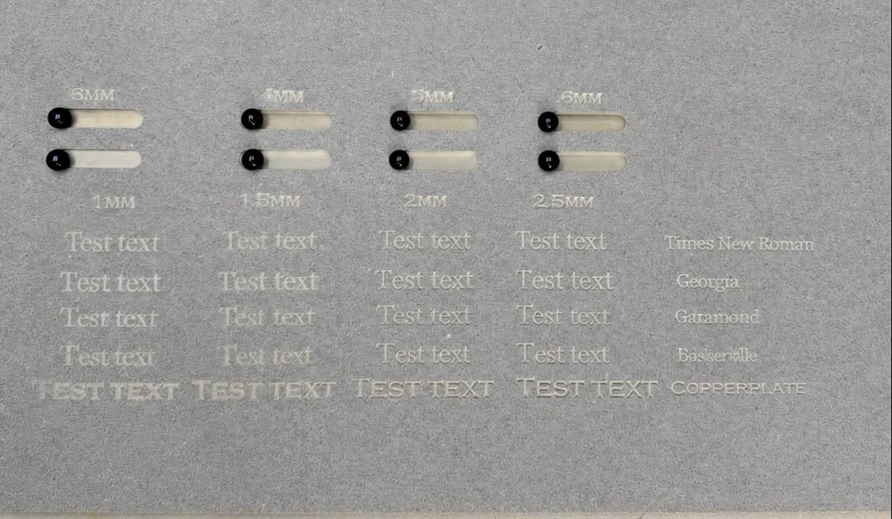
Internal workshop demonstration: a settings board containing routed slots, sample lettering and engraved details. Playing pieces placed in selected slots help compare the visible relationship between the component and the cut before progressing to a complete board.
The settings board isolates questions that would be harder to compare on a nearly complete part. Different slot labels and text samples are visible on one sheet, allowing the workshop to examine the test pieces and engraved detail side by side. This stage does not show which option was ultimately chosen, and the labelled values should not be transferred to another project without considering its actual material, tool and mating component.
For a new design, a similar coupon may be sufficient when the main uncertainty is one slot, pocket, corner or engraved feature. It can reduce the amount of material committed to an early decision while still creating something physical to inspect.
2. Full-size prototype
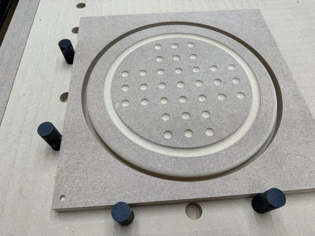
Prototype stage: a full-size MDF board on the CNC bed with the pocket pattern, circular channel and outside geometry visible together. The photograph records the prototype layout before any claim about a finished or assembled product.
The prototype combines the separate features into one overall board. Its value is contextual: spacing, visual balance, the relationship between pockets and channel, and the available border can now be considered on a physical, full-size piece. The image also shows workholding around the stock, which distinguishes the machining stage from a presentation-ready result.
MDF describes the material visible in this demonstration. It is not a recommendation that every game board should use MDF, nor does it establish how another sheet grade, coating or playing piece would behave.
3. Repeated sheet layout
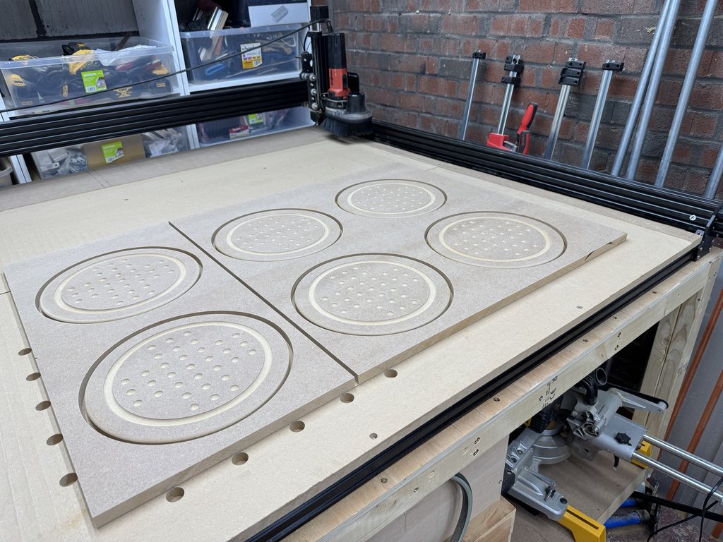
Repeated sheet layout: six instances of the circular board geometry are visible across two pieces of sheet material on the CNC bed before the components have been fully separated.
This stage shows the same visible pattern arranged more than once. Circular outlines, channels and pocket layouts can be compared across the sheet while the parts remain surrounded by stock. It is useful evidence that repeated geometry was machined in this particular workshop run.
The photograph does not establish the completed order quantity, machining time, material yield or future production capacity. Those depend on the approved file, stock, workholding, cutter strategy and quoted scope for each project.
For repeat products, the important transferable practice is to identify the approved part revision before arranging multiples. Quantity alone does not make a design ready for repetition. The prototype decision, machining file and later-stage responsibilities still need to be clear.
4. Parts after separation
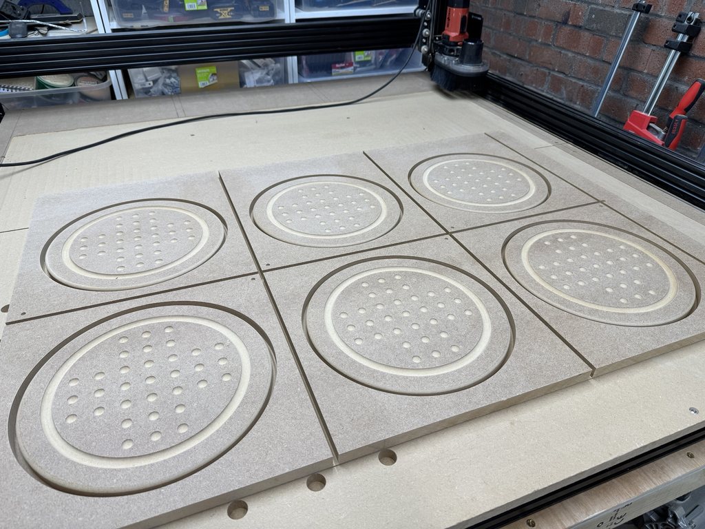
Parts after separation: the six machined sections have been divided from the larger sheet layout. Their circular profiles, channels and playing-piece pockets are visible, but the sections are still shown at a workshop stage.
This view is different from the previous one because the repeated sections can be seen individually. It makes the count and geometry easier to inspect without implying that the rectangular sections are finished products. Removing each round component from its surrounding stock, preparing edges, adding personalisation or applying a finish are separate stages unless a quotation expressly includes them.
For sellers ordering blanks, this distinction is particularly important. A quoted CNC stage may end with machined components, while the seller completes sanding, coating, assembly, retail inspection and packing. The handover point should be stated before production rather than inferred from a workshop photograph.
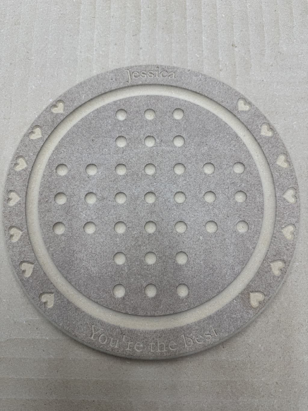
5. Personalised board after CNC machining
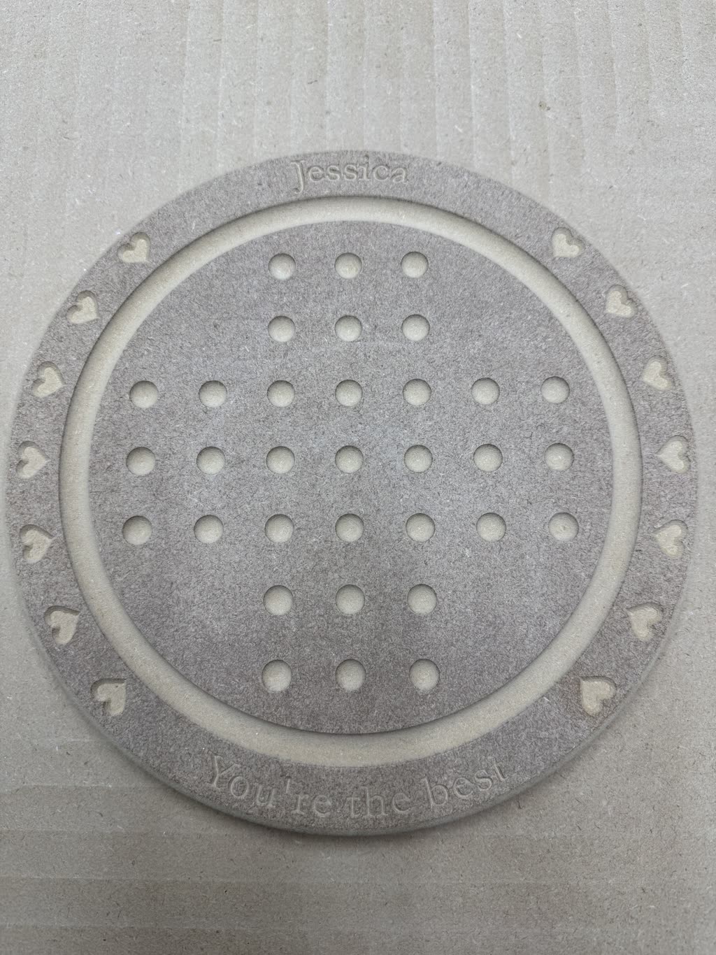
Completed CNC stage: one circular board has been removed from the surrounding sheet. The image shows the pocket pattern, routed channel, heart details and engraved wording; it does not show playing pieces, an applied coating or retail packaging.
This is the latest stage in the available sequence, but the accurate label is completed CNC stage, not finished assembled product. The board is visibly personalised and its outside profile has been cut. The photograph does not establish whether further edge preparation or finishing followed, whether the item was dispatched, or how anyone responded to it.
Keeping that boundary clear makes the example more useful. It shows what the CNC stage can look like without suggesting later work or outcomes that are not present in the photograph.
What the stages demonstrate
| Stage | What is visible | Useful question for another project |
|---|---|---|
| Settings test | Slots, playing pieces and engraved samples on one test board | Can the riskiest fit or detail be isolated before a full prototype? |
| Full-size prototype | One board layout with pockets, channel and outer geometry | Do the features make sense together at the intended scale? |
| Repeated layout | Six instances arranged across sheet material | Is the approved geometry and part revision ready to be repeated? |
| Separated sections | Individual machined sections on the CNC bed | Where does the quoted CNC stage end and later preparation begin? |
| Personalised CNC stage | A circular board with routed and engraved detail | Which finishing, inspection and packing stages remain after machining? |
Applying the sequence to a different idea
Another product does not need to copy every stage. The appropriate route depends on the consequence of the uncertainty.
If one piece of hardware must fit a pocket, a small representative test may answer the question. If several features interact across a whole part, a complete prototype may reveal issues that a coupon cannot. If the design will be repeated, approve the geometry and revision before committing material to a larger layout.
Differences in sheet material, thickness, finish, cutter access, playing pieces or intended use can justify a new test. The earlier demonstration is a process example, not a reusable manufacturing specification.
What to include in an enquiry
For a similar board or repeated component, send:
- a sketch, drawing or current vector/CAD file;
- overall dimensions and intended material;
- the size or physical sample of any item that must fit;
- the faces, pockets, engraving and profiles required;
- prototype and expected repeat quantities;
- the planned finish and who will complete it;
- a clear description of the feature that must be tested.
If you are not sure which machining terms apply, describe the intended result in ordinary language and mark up a photograph or sketch. The technical review can identify the missing decisions before a quotation is prepared.
Next step
Describe the uncertainty in your project, or read when to use a test cut or full prototype. No production work begins until the scope, price and approval requirements have been agreed.